
Table of Contents
A compound microscope consists of optical parts that magnify the specimen, illumination parts that control light, and mechanical parts that hold, move and focus the instrument.
The eyepiece and objective lenses produce the enlarged image. The illuminator, condenser and diaphragm control the light passing through the slide. The stage, focus knobs, arm and base keep the specimen and optical system correctly aligned.
This guide identifies the main parts of a compound microscope, explains what each one does and shows how the parts work together to create a clear image.
Microscope Parts at a Glance
A standard compound light microscope usually has between 10 and 15 major parts, depending on how individual controls are counted.
| Microscope part | System | Main function |
|---|---|---|
| Eyepiece or ocular lens | Optical | Magnifies the image formed by the objective |
| Head or body tube | Structural | Holds and aligns the eyepiece above the objectives |
| Revolving nosepiece | Mechanical | Holds and switches between objective lenses |
| Objective lenses | Optical | Form the primary magnified image of the specimen |
| Stage | Mechanical | Supports the slide |
| Stage clips or mechanical stage | Mechanical | Secure and move the slide |
| X-Y stage controls | Mechanical | Move the specimen horizontally and vertically |
| Condenser | Illumination | Concentrates light onto the specimen |
| Iris diaphragm | Illumination | Controls the light cone and affects contrast |
| Illuminator | Illumination | Provides light beneath the specimen |
| Coarse adjustment knob | Focusing | Makes large focusing movements at low power |
| Fine adjustment knob | Focusing | Makes small, precise focusing movements |
| Arm or frame | Structural | Connects and supports the upper and lower assemblies |
| Base | Structural | Supports and stabilizes the microscope |
The exact design varies. Some basic student microscopes use a disc diaphragm instead of an iris diaphragm, while more advanced microscopes may add binocular eyepieces, diopter controls, filters, cameras or motorized stage controls.
Labeled Parts of a Compound Microscope

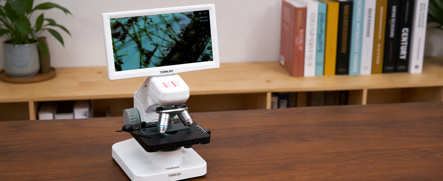
IMAGE PLACEMENT: Insert a clearly labeled compound microscope diagram here.
The diagram should identify:
- Eyepiece
- Head or body tube
- Revolving nosepiece
- Objective lenses
- Stage
- Stage clips
- Mechanical stage controls
- Condenser
- Iris diaphragm
- Illuminator
- Coarse adjustment knob
- Fine adjustment knob
- Arm
- Base
Although microscope designs differ, the same basic systems appear on most classroom and laboratory compound microscopes.
What Are the Three Main Systems of a Microscope?

The main parts can be organized into three functional systems.
Optical system
The optical system forms and magnifies the image.
Its main parts are:
- Objective lenses
- Eyepiece or ocular lens
- Internal tube lenses or prisms, depending on the design
The objective lens is primarily responsible for collecting light and resolving fine details. The eyepiece enlarges the image produced by the objective so it can be viewed comfortably.
Illumination system
The illumination system delivers controlled light through the specimen.
Its main parts are:
- Illuminator
- Condenser
- Iris or disc diaphragm
- Filters, when fitted
Increasing brightness does not always improve the image. Light must be focused and controlled to produce useful contrast and resolution.
Mechanical system
The mechanical system supports the microscope and positions the specimen.
Its main parts include:
- Head or body tube
- Nosepiece
- Stage
- Stage clips or mechanical stage
- Coarse and fine focus controls
- Arm
- Base
These parts must remain stable and correctly aligned. Even high-quality lenses cannot produce a consistently sharp image on an unstable frame or stage.
Optical Parts of a Microscope
1. Eyepiece or Ocular Lens
The eyepiece is the lens at the top of a traditional microscope that the user looks through. Most classroom microscopes use a 10x eyepiece, although other powers are available.
The eyepiece does not usually create the original image. Instead, it enlarges the intermediate image formed by the objective lens.
Total magnification is calculated as:
Total magnification = Eyepiece magnification × Objective magnification
A stronger eyepiece does not necessarily reveal more detail. Resolution is primarily limited by the objective lens, numerical aperture, illumination and optical quality.
For a more detailed explanation, read Microscope Magnification Explained.
2. Objective Lenses
The objective lenses are mounted on the rotating nosepiece directly above the specimen. They gather light from the sample and form the primary magnified image.
A typical compound microscope may include:
| Objective | Common name | Typical use |
|---|---|---|
| 4x | Scanning objective | Locating and centering the specimen |
| 10x | Low-power objective | Viewing general structures |
| 40x | High-dry objective | Observing individual cells and finer detail |
| 100x | Oil-immersion objective | Examining very small structures with immersion oil |
The objective has a greater effect on resolution than the eyepiece. Two objectives with the same magnification can produce different image quality if they have different numerical apertures or optical correction.
Our objective lens vs. ocular lens comparison explains these differences in more detail.
3. Revolving Nosepiece
The revolving nosepiece, also called the objective turret, holds the objective lenses and rotates them into the optical path.
Each objective should click securely into position. If the nosepiece stops between objectives, the image may become dark, partially obscured or impossible to focus.
Rotate the nosepiece using its textured edge rather than pushing directly on an objective lens. Avoid touching the glass or forcing a stiff mechanism.
4. Head or Body Tube
The head or body tube holds the eyepiece system above the objectives and maintains the required alignment between the optical components.
Depending on the microscope, the head may be:
- Monocular: one eyepiece
- Binocular: two eyepieces
- Trinocular: two eyepieces plus a camera port
A binocular head may also include interpupillary and diopter adjustments so each user can obtain a comfortable, balanced view.
Illumination Parts of a Microscope
5. Illuminator
The illuminator is the microscope’s light source. On a compound transmitted-light microscope, it is normally located in the base and directs light upward through the specimen.
Modern microscopes commonly use LEDs because they are efficient, cool and easy to control. Older microscopes may use halogen lamps or mirrors that reflect external light.
Brightness should be adjusted together with the condenser and diaphragm. Maximum brightness is not automatically the best setting.
6. Condenser
The condenser is positioned beneath the stage and focuses light onto the specimen.
Its job is not simply to make the image brighter. A correctly adjusted condenser helps the objective use light efficiently and supports both contrast and resolution.
Basic student microscopes may have a fixed condenser. More advanced microscopes often use a height-adjustable Abbe condenser.
At higher magnification, condenser position becomes increasingly important. If the illumination is uneven or the image lacks detail, condenser adjustment may be necessary.
7. Iris Diaphragm
The iris diaphragm is an adjustable opening located below the stage, usually as part of the condenser assembly.
It controls the angle and amount of light entering the objective. Changing the diaphragm affects:
- Brightness
- Contrast
- Depth of field
- Resolution
- Visibility of transparent specimens
Partially closing the diaphragm may make a pale specimen easier to see, but closing it too far reduces resolution and can create unwanted diffraction.
The diaphragm and condenser work together but do different jobs:
- The condenser focuses light onto the specimen.
- The diaphragm controls the light cone entering the optical system.
Read What Is the Function of the Diaphragm on a Microscope? for a deeper explanation.
Specimen-Holding and Movement Parts
8. Stage
The stage is the flat platform that supports the slide. A central opening allows transmitted light to pass through the specimen and enter the objective.
The stage should remain clean and dry. Liquid, immersion oil and broken glass can interfere with movement and damage the microscope.
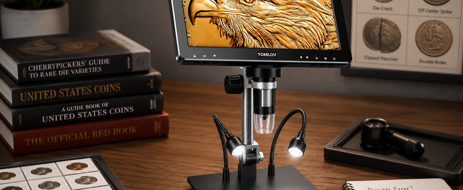
Some digital inspection microscopes use a work platform instead of a slide stage because they are designed for solid objects such as coins or circuit boards.
9. Stage Clips
Stage clips hold the slide against the stage on a basic microscope.
They are simple and inexpensive, but manually moving a slide beneath fixed clips can be difficult at high magnification. A small movement may move the target completely out of the field of view.
10. Mechanical Stage
A mechanical stage secures the slide in a movable holder. It allows much more precise specimen positioning than basic stage clips.
A mechanical stage is especially useful when:
- Scanning a slide systematically
- Following a moving organism
- Returning to a specific structure
- Working at 400x or higher
- Counting objects across multiple fields
11. X-Y Stage Controls
The X-Y controls move the mechanical stage in two directions:
- X-axis: left and right
- Y-axis: forward and backward
At high magnification, move the controls slowly. Because a compound microscope usually produces an inverted image, the apparent direction of specimen movement may initially feel reversed.
Focusing Parts of a Microscope
12. Coarse Adjustment Knob
The coarse adjustment knob makes relatively large movements of the stage or optical assembly.
Use it to find the general focus at the lowest magnification. It should not normally be used with a 40x or 100x objective close to the slide because a large movement can drive the objective into the coverslip.
A safe focusing sequence is:
- Select the 4x scanning objective.
- Watch from the side while bringing the objective near the slide.
- Look through the eyepiece.
- Use coarse focus to find the specimen.
- Center the target.
- Switch to a higher objective.
- Use fine focus to sharpen the image.
13. Fine Adjustment Knob
The fine adjustment knob moves the stage or objective in much smaller increments.
It is used to:
- Sharpen fine details
- Focus at 40x and higher objectives
- Move through different planes of a thick specimen
- Correct small focus changes after switching objectives
A microscope that remains nearly in focus after objectives are changed is described as parfocal. Even on a parfocal microscope, small fine-focus adjustments may still be necessary.
For additional examples, see Functions of Fine and Coarse Adjustment Knobs.
Structural Parts of a Microscope
14. Arm or Frame
The arm connects the microscope’s head to its base and supports the optical assembly.
On a traditional classroom microscope, the arm is also one of the safe carrying points. Use one hand to hold the arm and place the other hand beneath the base.
Do not carry a microscope by:
- The eyepiece
- The stage
- A focus knob
- The nosepiece
- A camera cable
- An LCD screen
A rigid arm also helps maintain optical alignment. Flex or vibration in the frame becomes more visible as magnification increases.
15. Base
The base supports the microscope and helps resist vibration. It may also contain:
- The illuminator
- Power electronics
- Brightness controls
- A power switch
- Batteries or an external power connection
A wide, rigid base generally provides better stability. A lightweight base may be more portable, but it can move when the focus or stage controls are adjusted.
How Microscope Parts Work Together

A microscope does not create a clear image through magnification alone. The optical, illumination and mechanical systems must work together.
The basic light path is:
Illuminator
↓
Diaphragm
↓
Condenser
↓
Specimen
↓
Objective lens
↓
Head or body tube
↓
Eyepiece
↓
Viewer’s eye
The process works as follows:
- The illuminator produces light.
- The diaphragm controls the light cone.
- The condenser focuses light onto the specimen.
- The specimen changes or absorbs part of the light.
- The objective collects the transmitted light and forms a magnified image.
- The eyepiece enlarges that image for the viewer.
- The stage positions the specimen.
- The focus controls place the specimen in the sharp focal plane.
- The arm and base keep the entire optical path stable.
A blurry image can therefore be caused by more than incorrect focus. Possible causes include unsuitable lighting, a misplaced condenser, a dirty objective, an unstable stage or an objective that is not fully clicked into position.
Which Microscope Parts Control Magnification?
On a compound microscope, the objective and eyepiece determine total magnification.
For example:
| Eyepiece | Objective | Total magnification |
|---|---|---|
| 10x | 4x | 40x |
| 10x | 10x | 100x |
| 10x | 40x | 400x |
| 10x | 100x | 1000x |
Magnification should not be confused with resolution.
Magnification determines how large the image appears. Resolution determines whether two nearby details can be distinguished. Enlarging an image beyond the optical system’s resolving ability creates empty magnification—a larger but not clearer image.
Which Microscope Parts Affect Image Quality Most?
Several parts directly influence image quality.
Objective lens
The objective has the greatest effect on optical detail, numerical aperture, field of view and working distance.
Condenser and diaphragm
These parts control how light reaches the specimen and enters the objective. Incorrect illumination can make a correctly focused image appear flat or unclear.
Focus controls
Fine focus selects the correct focal plane. At higher magnification, depth of field becomes smaller, so precise focusing is essential.
Stage
An unstable or poorly controlled stage makes it difficult to keep the target centered.
Eyepiece
The eyepiece must display the objective image comfortably without introducing obvious distortion. A stronger eyepiece cannot compensate for a low-resolution objective.
Frame and base
Movement and vibration become increasingly visible at higher magnification. Stability is therefore part of image quality, not merely a convenience.
Traditional and Digital Microscope Parts Compared
Digital microscopes add electronic imaging components that are not found on a basic optical compound microscope.
| Traditional compound microscope | Digital microscope |
|---|---|
| Eyepiece | LCD screen or external monitor |
| Objective lenses | Fixed or interchangeable digital lens |
| Human eye views the image | Camera sensor captures the image |
| Transmitted illumination | Reflected, side or transmitted lighting |
| Coarse and fine focus knobs | Focus wheel, stand movement or autofocus |
| Slide stage | Slide stage or solid-object work platform |
| Visual observation | Photos, video and digital storage |
| No image processor required | Image processor controls digital output |
Camera sensor
The camera sensor converts the image produced by the lens into electronic data. Sensor resolution matters, but it cannot recover details that the lens failed to resolve.
Image processor
The processor controls exposure, color, sharpening, noise reduction and video output. Excessive digital sharpening can create artificial-looking edges without revealing real detail.
LCD screen
The screen displays the live image. A larger screen makes viewing more comfortable but does not increase the optical detail captured by the microscope.
HDMI and USB ports
HDMI sends live video to an external monitor. USB may support computer viewing, file transfer, power or measurement software, depending on the model.
Storage
Many digital microscopes save photographs and videos to a microSD card or connected computer.
LED ring and side lights
Digital inspection microscopes often illuminate opaque surfaces from above. This design works well for coins, circuit boards and mechanical parts but differs from the transmitted-light system used for biological slides.
For a complete comparison, read Digital vs. Optical Microscope.
Common Mistakes When Using Microscope Parts
Using coarse focus at high power
The coarse knob moves too far for safe focusing with a high-power objective. Use fine focus after switching to 40x or 100x objectives.
Touching optical glass
Fingerprints reduce contrast and can damage coatings. Handle objectives and eyepieces by their metal housings.
Rotating objectives by pushing the lenses
Turn the nosepiece by its edge instead. Pushing an objective can affect alignment or leave fingerprints.
Using immersion oil on the wrong objective
Immersion oil is generally intended only for an objective specifically marked for oil immersion, commonly a 100x objective.
Do not place oil on a normal 40x dry objective. After using oil, clean the oil-immersion objective according to the manufacturer’s instructions.
See How to Use Microscope Immersion Oil before using a 100x oil objective.
Assuming maximum brightness is best
Excessive illumination can reduce visible contrast. Adjust the illuminator, condenser and diaphragm together.
Carrying the microscope with one hand
Use one hand on the arm and the other beneath the base. Do not lift the instrument by a removable or adjustable component.
How to Clean and Maintain Microscope Parts
Follow the manufacturer’s cleaning instructions for the specific microscope.
General precautions include:
- Remove loose dust before wiping a lens.
- Use lens paper rather than ordinary facial tissue.
- Do not apply household glass cleaner to optical surfaces.
- Keep immersion oil away from dry objectives.
- Clean oil from an oil-immersion objective after use.
- Keep liquids away from power switches and electronic ports.
- Do not force stiff controls.
- Cover the microscope when it is not in use.
- Store objectives in the lowest safe position.
- Keep cables loosely arranged rather than tightly bent.
For detailed optical cleaning instructions, see How to Clean a Microscope Lens.
Frequently Asked Questions
What are the main parts of a microscope?
The main parts include the eyepiece, objective lenses, revolving nosepiece, head, stage, stage controls, condenser, diaphragm, illuminator, coarse and fine focus knobs, arm and base.
What are the three main systems of a microscope?
The three main systems are optical, illumination and mechanical. Digital microscopes also include an electronic imaging system containing a sensor, processor, display and storage components.
Which part of a microscope provides the main magnification?
The objective lens produces the primary magnified image and has the greatest influence on resolution. The eyepiece magnifies that image again for viewing.
Which part holds the objective lenses?
The revolving nosepiece holds the objective lenses and rotates each one into the optical path.
Which part holds the microscope slide?
The stage supports the slide. Stage clips or a mechanical stage secure it, while X-Y controls move it precisely.
What is the difference between coarse and fine adjustment?
Coarse adjustment makes large focus changes and is mainly used at low power. Fine adjustment makes small, precise changes and is used at medium and high magnification.
What does the condenser do?
The condenser concentrates and focuses light onto a transparent specimen. Correct condenser adjustment supports even illumination and useful resolution.
What does the diaphragm do?
The diaphragm controls the amount and angle of light entering the optical system. It affects brightness, contrast, depth of field and resolution.
Which parts determine total magnification?
The eyepiece and objective determine total magnification on a compound microscope. Multiply their powers to calculate the total.
Do digital microscopes have eyepieces?
Some do, but many replace the eyepiece with a camera sensor and LCD screen or external monitor.
What is the safest way to carry a microscope?
Hold the arm with one hand and support the base with the other. Keep the microscope upright and close to the body.
Can immersion oil be used on a 40x objective?
Not unless that particular objective is specifically designed and marked for immersion. Standard 40x high-dry objectives should not be used with oil.
Final Answer
The main parts of a compound microscope belong to three systems:
- Optical parts—the objective lenses and eyepiece form and magnify the image.
- Illumination parts—the illuminator, condenser and diaphragm control light.
- Mechanical parts—the stage, focus knobs, nosepiece, arm and base position and stabilize the instrument.
Learning the name of each component is useful, but understanding how the parts interact is more important. A clear microscope image depends on suitable objectives, controlled illumination, precise focusing, careful specimen movement and a stable frame working together.


Hinterlasse einen Kommentar
Alle Kommentare werden vor der Veröffentlichung geprüft.
Diese Website ist durch hCaptcha geschützt und es gelten die allgemeinen Geschäftsbedingungen und Datenschutzbestimmungen von hCaptcha.