
Table of Contents
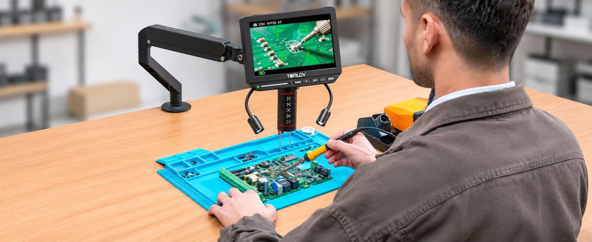
The best USB digital microscope for electronics depends on what you do at the bench. If you mainly check solder joints, read chip markings, or take close-up photos, a compact USB microscope may be all you need. If you solder while watching a screen, you’ll also want enough room for an iron and tweezers, a stable stand, and a live feed that keeps up with your movements.
Top Picks by Workbench Task
|
Model |
Best for |
Viewing options |
Main trade-off |
|
TOMLOV TM4K-AF Flex |
PCB inspection, SMD rework, and saving repair photos |
8-inch built-in screen, HDMI monitor, or USB live view on a computer |
Takes up more bench space than a compact USB scope |
|
Plugable USB Digital Microscope 250x |
Quick PCB checks, reading chip markings, and taking close-up photos |
USB live view on a computer |
Limited tool clearance for soldering under the lens |
|
Andonstar AD246S-M |
Switching between wider board views and close-ups of pins and pads |
Built-in screen, HDMI monitor, or USB live view on a compatible computer |
Switching lenses adds a step when you change views |
TOMLOV TM4K-AF Flex for PCB Inspection and SMD Rework
Best for:
A repair bench where you inspect boards, replace SMD components, and save photos of the finished work.
What you’ll use most:
Articulating arm. Move the camera over a connector near the edge of the board while leaving the board in its holder.
Autofocus and two focus presets. Save one focus position for the top of a tall connector and another for the pads beside it. Use P1 and P2 to switch between them.
Two adjustable side lights. Change the angle of the light to reduce glare on shiny pins or solder joints.
Three viewing options. Use the 8-inch screen for quick checks, HDMI for a larger view during rework, or USB to capture repair photos on a compatible computer.
What to consider
Allow room for the base and for the arm to swing over the board. The TOMLOV TM4K-AF Flex is easiest to justify if you regularly do both inspection and rework at the same bench.

Plugable USB Digital Microscope 250x for Quick PCB Checks
Best for:
Reading chip markings, checking for a bent connector pin, or photographing a solder joint when you already have a computer on the bench.
What you’ll use most:
USB camera connection. View the board in an app such as Windows Camera or Photo Booth on a Mac.
Manual focus wheel. Bring the camera closer to the board for a tighter view, then turn the wheel until the detail is sharp.
Compact stand. Keep the camera in place while you reposition the board or take a photo.
What to consider
Moving the camera closer leaves less room for an iron and tweezers. This setup is best suited to inspecting joints before or after soldering.
Andonstar AD246S-M for Inspection at Multiple Scales
Best for:
A bench where you regularly switch between a wider view to locate a problem and a close-up to inspect individual pins or pads.
What you’ll use most:
Interchangeable lenses. Start with a wider view to locate a damaged connector, then switch lenses when you need a closer look.
Longer-distance soldering lens. Andonstar lists a 90–300 mm focus range for Lens L. The clearance you’ll actually use depends on how much detail you need to see.
Multiple viewing options. Check the board on the built-in screen, connect a larger monitor over HDMI, or use USB live view on a compatible computer.
What to consider
Each lens change adds a setup and refocusing step. If you work on similar boards most days, check whether the soldering lens alone covers the views you use most.
What to Look for in a PCB Inspection Microscope
Field of View and Image Detail
Start by looking at how much of the board fits in one frame. For a connector, seeing the whole row of pins makes it easier to spot one that sits out of line. A closer view can then help you check for a bridge between two pins or see whether a pad has lifted. When comparing microscopes, look for sample images of the kinds of boards you work on. They tell you more about usable detail than the maximum magnification on the box.
Lighting and Glare Control
Shiny solder can reflect light back into the lens and wash out the edges of a joint. Adjustable side lights let you move the reflection away from the area you want to inspect. They’re also useful around tall components, where light from directly above can leave nearby pads in shadow.
What Matters When Soldering Under a Microscope
Working Distance and Tool Clearance
Working distance is the gap between the lens and the board when the image is in focus. Check that gap at the level of detail you’ll actually use for soldering. There should be room to bring in an iron and tweezers at a comfortable angle while keeping both tips in view. If you use a PCB holder, include it when you check clearance because it raises the board.
Stand Stability
Check how the stand feels when the camera is positioned over the edge of a board. An arm that’s steady near its base may move more when fully extended. If a small adjustment sends the image shaking, you’ll have to wait for it to settle every time you reposition the camera.
Video Lag and Depth Perception
Move a pair of tweezers across the board and watch the tip on screen. If the picture trails your hand, placing a tiny component can feel awkward. A single-camera view can also make it harder to judge how far the tip is above the board. If most of your work involves fine, hands-on rework, compare that experience with the depth you get through a stereo microscope.
When to Use USB, HDMI, or a Built-In Screen
USB for Live Viewing and Image Capture on a Computer
USB is useful when you want to save inspection photos directly to a computer or share a live view. Check that the microscope supports live video over USB and works with your operating system. Some USB ports are used only for power or file transfers. On the TM4K-AF Flex, UVC camera mode sends a live image to a compatible computer app, while storage mode lets you transfer files you’ve already saved.
HDMI for Viewing on an External Monitor
HDMI is useful when you want a larger screen for following a row of fine pins or watching your tool tips during rework. The microscope connects directly to the monitor, so you can keep a computer off the bench. If resolution or frame rate matters to you, check the HDMI output specs separately from the microscope’s recording specs.
A Built-In Screen for Standalone Work
A built-in screen is convenient when bench space is limited or you only need a quick look. You can check a connector or inspect a finished repair without opening an app or setting up a second display. Screen size matters most when you spend long stretches following small components across a board.
Frequently Asked Questions
Can a USB Microscope See Solder Joints Under a BGA Chip?
A USB microscope can show the edges of the package and the components around it. The solder balls sit underneath the chip, outside the lens’s line of sight. X-ray inspection can help evaluate those hidden joints.
Can a Microscope Tell If a Solder Joint Is Electrically Sound?
A microscope can reveal visible problems such as solder bridges, lifted pads, and some cracks. A joint can look fine and still have an electrical fault. To confirm the connection, use an electrical test appropriate to the circuit.

Leave a comment
All comments are moderated before being published.
This site is protected by hCaptcha and the hCaptcha Privacy Policy and Terms of Service apply.